FAQ: How to Choose a Correct Delay Range for Your Timegated® Raman Measurement Results?
FAQ series: This series of publications explores some of the most frequently asked questions regarding Timegated® spectrometers and measurements without having you read page after page of text.
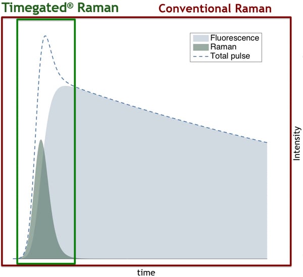
Timegated® Raman measurements produce time-resolved spectral information which means that the temporal aspect should be considered when choosing optimal measurement and processing settings. Once the parameters are optimized for a certain sample type and measurement setup, the settings do not usually need further adjustment afterward.
Below is an example of a time-resolved spectrum with signal, Raman shift, and delay axes. If the user is only interested in the Raman responses, only the delay range that contains Raman information is included in the final result. Alternatively, if the fluorescence properties are of interest, information from a wider delay range may be included. In this text, we presume that the operator is solely interested in the Raman responses and the aim is to minimize any fluorescence interference.
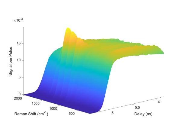
A time-resolved spectrum produced by a Timegated® spectrometer.
How to Decide on an Optimal Measurement Delay Range?
With many samples, the first clue might be the protrusions in the forefront of the signal pulse caused by Raman responses. These Raman responses give an initial indication of what the optimal delay range might be. The delay range can be inspected with more clarity when looking at a side projection of the “3D” spectra from the intensity vs. delay direction.
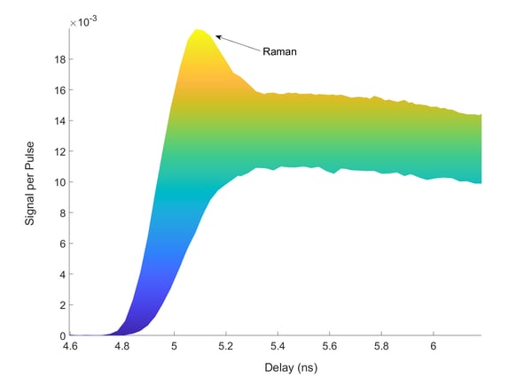
With many samples, the Raman responses can be observed at the forefront of the signal pulse.
With some of the more challenging samples, the Raman responses might not be as easily distinguishable. A generally useful approach is to first measure a sample that is known to have high-intensity Raman responses and very little fluorescence. In this example, cyclohexane is used as this reference sample. Once the cyclohexane is measured, the delay range where the Raman responses are located is known and it is possible to start to decide which delay ranges might be included and excluded in the end result. The Raman scattering delay range rarely changes from sample to sample if the measurement setup is kept constant.
The general idea is to exclude later parts of the delay range where most of the fluorescence emission is located; this technique is called virtual gating. Temporal overlap of Raman and fluorescence is not uncommon and with some challenging samples, we might decide to exclude a part of the Raman delay range to get rid of some of the overlapping fluorescence. This compromise leads to sacrificing some of the Raman intensity to reduce fluorescence interference even further.
In the figure below, two delay ranges are indicated with yellow and red boxes. The red delay range indicates a range that should be excluded from most end results as this range doesn’t include any significant amount of Raman information. The yellow range could be excluded with more challenging samples with high fluorescence intensities and potential overlap of fluorescence and Raman. Excluding the yellow delay range will lead to collecting slightly less Raman scattering while suppressing fluorescence interference even further. 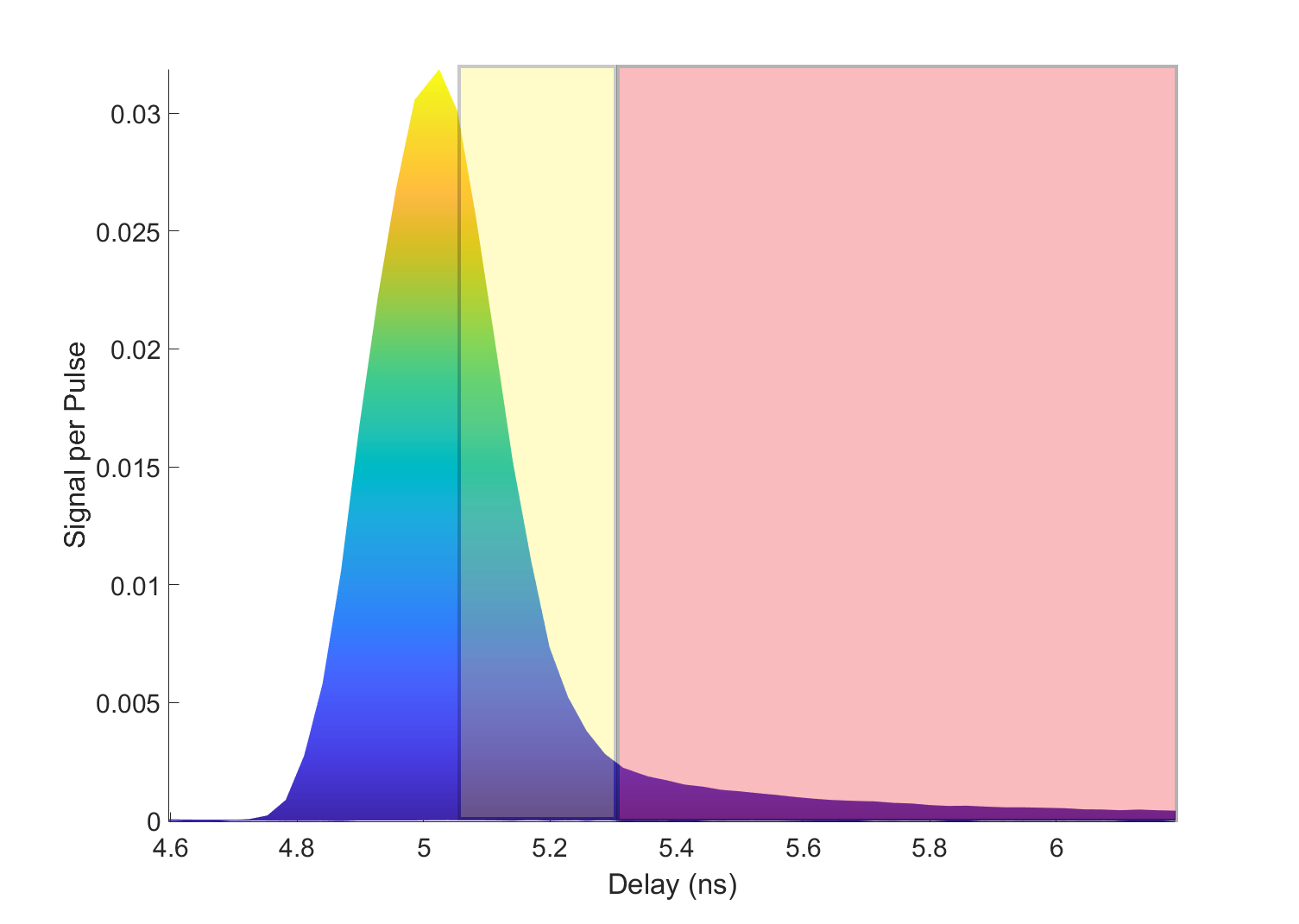
The optimal delay ranges can initially be estimated by using a known reference sample with low fluorescence levels. Excluding the yellow delay range from measurements also excludes some of the Raman intensity, but this may be necessary to exclude some of the overlapping fluorescence emission.
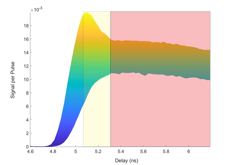
The delay ranges defined using a reference sample can then be applied to new samples.
Once the delay ranges have been defined using the reference sample, they can be applied to other measurements. The included delay range defined using a reference sample is usually adequate for most purposes but further optimization can be carried out for different sample types by varying the included delay range and checking the results. The spectra processing software provided with Timegated® Raman spectrometers enables the option to retroactively exclude chosen delay ranges from the final spectra.

Author
 This blog was written by Timegate Instruments’ Application Team Lead Bryan Heilala. Bryan is a young and energetic chemist with a degree in M.Sc. (chemistry) and experience and background in analytical chemistry.